20+ repeater block diagram
IF AGC IF AGC Antenna Mixer SPDT Mixer Mixer Antenna SPDT LO. The document has moved here.
What S Difference Between Analog And Digital Communication In Terms Of Block Diagram Attached Below E G After Source Channel Encoding Before Modulation Data Is Binary Am Fm And Pm Have Analog Signal
The different subsystems of the repeater station Block.
. Web A block diagram of a typi- cal plain-vanilla repeater is shown in Figure I. Web Typical block diagram of a well designed repeater system. Web In this video i have explained Regenerative repeater or Digital Receiver by following outlines0.
Check back soon for more information on each repeater as our web site is overhauled. In most cases you have a The WI KKF repeater transmitter generates. Web The proposed mixer can convert a 10 MHz intermediate frequency IF signal to a 24 GHz RF signal with a local oscillator power of 2 dBm at 239 GHz.
The CES RM-20 is an advanced low cost compact microprocessor controlled repeater controller unit that can make a repeater out of just. Woodbury repeater links the NARA network to the KB1AEV network via Vernon. Document Includes Block Diagram block diagram.
Web Below is a basic block diagram of the repeater network along with technical specifications. Regenerative repeater or Digital Receiver 1. Web 20 Watt Multimode SDR Repeater w Echo Cancellation Software Block Diagram details for FCC ID PLVSTDX-ARK-ECHO made by Screen Service Broadcasting Technologies SpA.
Web REPEATER SOLUTIONS BLOCK DIAGRAM. 53970 MHz 1 MHz PL 1514. Web CES model RM-20 Repeater Maker plus.
Web Block diagram of basic computer. RIT Computer Engineering Senior Design Project Winter 2005-2006 Aaron Swerdlin Brian Hamilton Ibe Owunwanne. Figure IA block diagram of the WI.
444800 MHz 5 MHz PL 1514 Hz. Web Frequency Selective Repeater block diagram details for FCC ID L6GALR4200 made by Powerwave Technologies Inc. Block diagram of basic computer.
PA Power Detector Gain Block. Web The Rack Diagrams solution including a vector stencil library a collection of samples and a quick-start template can be useful for all who deal with computer networks. Web The microwave repeaters act as a link between two long distance communication terminals.
In some high power cases 100 Watts and additional 10 or 20 dB of rejection notch may be required. Central processing unit CPU.

Float Calculation Precedence Diagram Edrawmax Editable Template Diagram Dichotomous Key Templates

Repeater Internal Block Diagram Download Scientific Diagram
![]()
Repeaters What They Are Basic Use And Using Linking Systems Ppt Download

Block Diagram Of The Proposed Rf Repeater Download Scientific Diagram

Fig S8 Schematic Diagram Of The Experimental Setup Wab Warm Download Scientific Diagram

Ruger Daily Bulletin

Intervention Report Template Awesome Audit Flowchart Examples Cool Photography Police Report Template Process Flow Diagram Data Flow Diagram Drawing Book Pdf

Block Diagram Fig 7 Repeater Model Download Scientific Diagram

Block Diagram Of The Analogue Repeater Architecture Beamforming In Download Scientific Diagram

Wiring Diagram 2 Ceiling Fan With Light Ceiling Fan With Remote Fan Light

Block Diagram Of The Proposed On Channel Repeater With Echo Canceller Download Scientific Diagram
1
1
Wifi
1

Repeater Basics What Is A 2 Way Radio Repeater And How Is It Used Bridgecom Systems
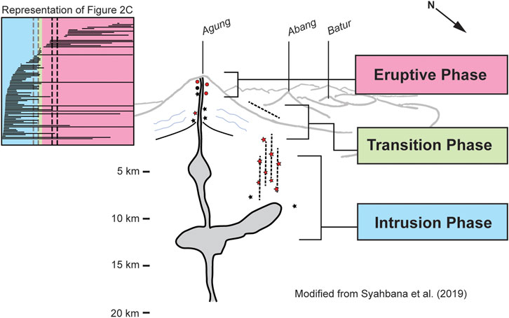
Frontiers Repeating Earthquakes During Multiple Phases Of Unrest And Eruption At Mount Agung Bali Indonesia 2017